Get in touch with Cenwan Machine Company

Printing Die Cutting Folding Gluing Line: 7 Quality Gates for Stable Output

Operational Engineering Guide
A printing die cutting folding gluing line is an integrated carton-production system that moves material and job data through printing, cutting, creasing, folding, adhesive application, compression, counting, and delivery. It operates as one system only when quality evidence, machine status, rejects, and safety states also cross module boundaries. This guide helps plant managers, QA teams, procurement specialists, and owners analyze those interfaces through measurable acceptance criteria.
Prepared for CENWAN. Supporting facts and global standards scopes are independently cited below.
Scope: this is an operational guide to interfaces, bottlenecks, defect causes, changeovers, and FAT/SAT evidence. Product models, configurations, pricing, ROI calculations, and quotation requests remain on the commercial solution page.
What a printing die cutting folding gluing line actually connects
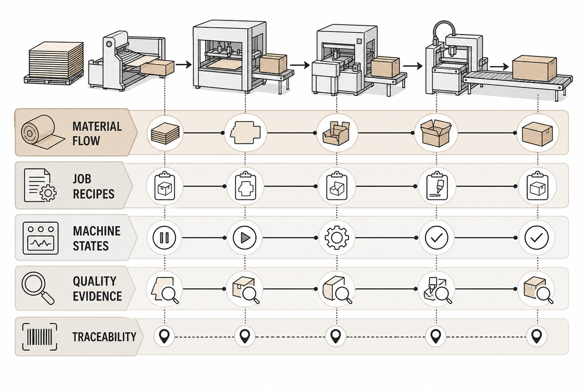
Direct answer: a single, integrated line produces conforming cartons that start at the feeder, pass through registered printing, rotary cutting and creasing, blank separation and transfer, folding, synchronized adhesive application, compression, automatic counting, and stack delivery without losing job identity, piece-level quality records, or material history. This physical sequence turns the interface and defect scope above into measurable handoffs.
The University of Bologna’s folding-gluing process description follows the physical sequence: align, fold, apply adhesive, compress, and stack. That sequence matters because a module can work correctly in isolation while a poor handoff sends defects downstream.
Translate plant vocabulary before comparing a line
Carton packaging terms describe several architectures, so labels are not specifications. A folding carton packaging or bindery workflow may send printed products from letterpress or another print process to a standalone die-cutting machine, while a corrugated board plant may use inline machinery for carton production. “Diecutting” is an alternate spelling; neither it nor “die-cutter” proves that the printing, die-cutting process, folding and gluing are synchronized.
Design vocabulary has its own boundary. Computer-aided design (CAD) defines the final design, cut lines, fold lines, perforation, emboss locations, and each tab. When a custom die is created, steel rule or other approved tooling is used to cut out the shape. Record the material to cut, compare cutting methods, and document any specific shapes instead of assuming that one tool suits every substrate.
Production labels also need conditions. A short-run or high-volume manufacturing process can use the same equipment name while demanding different changeover records, quality control sampling, downtime codes, operator training, and precision thresholds. A carton manufacturer should define those measures before calling any arrangement a packaging solution.
Custom packaging and customized packaging may describe the same market, but not the same acceptance test. To create packaging consistently, the finisher must define how blanks are glued and folded, where compression will apply pressure, and what evidence releases final packaging. Those interface controls, not the label alone, determine whether a line can produce custom packaging reliably.
Five things must move together:
- Material flow: sheets, webs, blanks, folded cartons, rejects, and counted bundles.
- Job recipes include parameters related to the specific project, such as the edition of artwork, the format of the die, the specifications of the board material, the required tools, fold settings, the adhesive pattern, and the acceptance rules for a satisfactory result.
- Machine status conditions signify various operational states: the line is prepared to run, in active operation, waiting for input, halted by obstruction, signaling an error, in a safe stop procedure, or awaiting restart authorization.
- Quality evidence that must be captured includes sheets that meet alignment requirements, evidence of crease consistency, glue-pattern verification, confirmation of bond integrity, and the total number of accepted cartons.
- Traceability: link each result to the job number, material lot, recipe revision, operating shift, and documented deviations.
If one of these system layers fails, the line may keep producing while losing the carton-level history needed to explain output trends, scrap, or seam-quality variation.
The 7 process interfaces where defects travel downstream
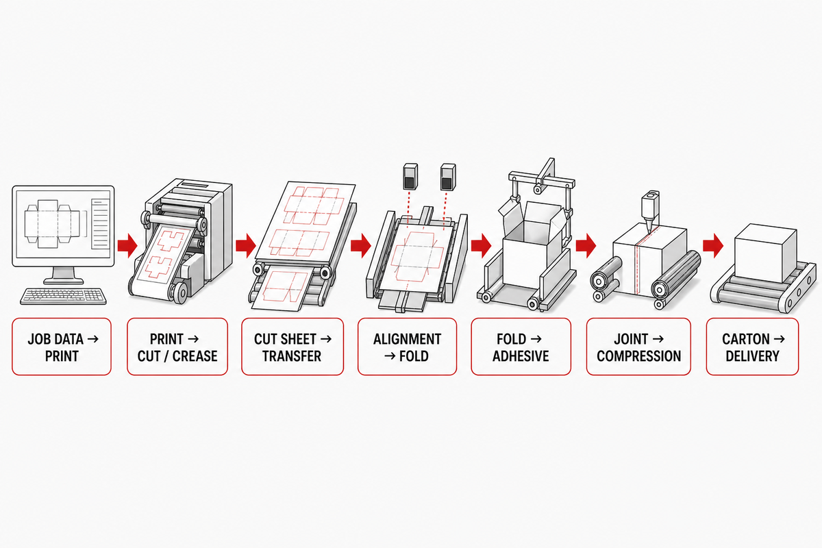
Direct answer: the critical interfaces are job data to printing, print to cut/crease, cut sheet to blank transfer, blank alignment to fold initiation, fold position to adhesive timing, adhesive joint to compression, and compressed carton to counted delivery. Each boundary needs an input condition, state signal, reject rule, and confirmation sample. Those seven checks preserve the carton-level history and job data defined in the preceding section.
Asset 1: the 7-Interface Quality Chain
| # | Handoff | Evidence entering | What can travel downstream | Release check |
|---|---|---|---|---|
| 1 | Stock and job data → printing | Approved artwork, stock lot, color standard | Wrong revision, unstable sheet condition, coating mismatch | Job identity and first-approved sheet |
| 2 | Printed sheet → cut and crease | Print register, dieline revision, tool identity | Print-to-cut drift, weak nicks, misplaced crease | Register sample and crease evidence |
| 3 | Cut/creased sheet → stripping and transfer | Blank integrity, edge quality, stripping result | Premature breakup, debris, skew, double feed | Blank transfer without damage |
| 4 | Blank alignment → pre-fold and fold | Reference edge, crease location, blank flatness | Fishtailing, panel mismatch, cracking | Controlled fold path and panel meeting |
| 5 | Fold position → adhesive application | Glue-flap position, recipe, surface condition | Missed glue, squeeze-out, contaminated print | Pattern presence and location |
| 6 | Adhesive joint → compression | Joint alignment, adhesive state, pressure path | Open seam, spring-back, scuff, set-off | Seam result after defined conditioning |
| 7 | Compressed carton → counting and delivery | Accepted/rejected identity and count | Mixed status, unstable stack, count error | Reconciled good count and reject count |
For each row (1-7 above), assign one owner to ensure a good input signal, one owner to acknowledge received work and collect verification data, and one contact for a failed release check, such as a nonconforming item or machine-status warning. This operational handoff map complements, but does not replace, the safety requirements for converting equipment and systems in ISO 12643-4:2023.
Balance the line before selecting peak speed
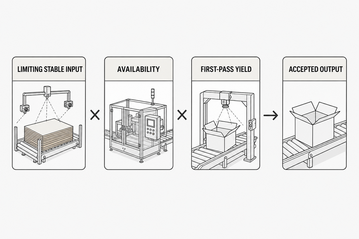
Direct answer: identify the module or interface that consistently limits total accepted production volume when running a specific job, and separate its availability from the impact of individual job quality defects. The seven-interface chain above identifies where to collect each input. This analysis doesn’t focus on maximum module speed. As a first step, multiply a module’s best stable input rate by its overall calculated availability and measured overall first-pass yield for the given job.
First-pass calculation: accepted output = limiting stable input rate × availability × first-pass yield.
Hypothetical example only, not an industry benchmark: a trial job enters the limiting interface at 12,000 sheets/hour. Recorded availability for the same window is 85%, and first-pass yield is 97%. This calculation gives 12,000 × 0.85 × 0.97 = 9,894 accepted cartons/hour. Replace every input with measured job data.
This equation is deliberately narrow. A 2018 NIST paper on multi-job serial lines shows that throughput and bottlenecks can change with product mix. It’s used here as a foundational modeling reference, not as a current machine standard. Build sequence, finite buffers, starvation, blocking, and different processing times can move the constraint. Treat the arithmetic as a clue, then test whether the same constraint persists across the planned SKU mix.
Asset 2: Bottleneck Budget Worksheet
| Station or interface | Job/SKU | Stable input rate | Loss class | Evidence window | Accepted rate |
|---|---|---|---|---|---|
| Printing → cut/crease | Enter SKU | Enter cartons/hour | Starved / blocked / stop / reject / fault | Enter start and end | Enter cartons/hour |
| Blank transfer → folding | Enter SKU | Enter cartons/hour | Starved / blocked / stop / reject / fault | Enter start and end | Enter cartons/hour |
| Gluing → compression | Enter SKU | Enter cartons/hour | Starved / blocked / stop / reject / fault | Enter start and end | Enter cartons/hour |
| Compression → delivery | Enter SKU | Enter cartons/hour | Starved / blocked / stop / reject / fault | Enter start and end | Enter cartons/hour |
Real constraints repeat. Change one condition and watch whether accepted deliveries change with it. If the apparent constraint shifts with your SKU sequence, document a product-mix bottleneck map instead of declaring one machine the permanent bottleneck.
Substrate, print, crease, and glue interactions
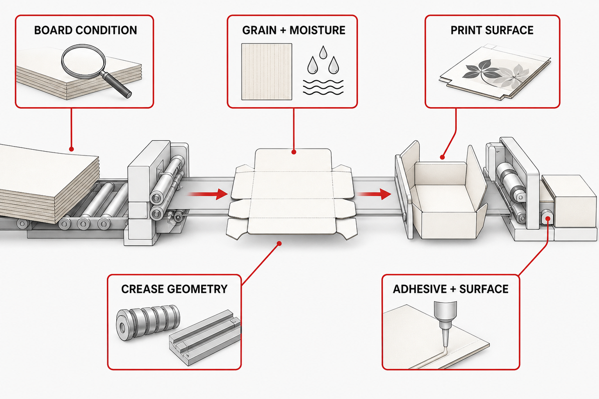
Direct answer: board grade, grain, moisture, thickness, surface finish, ink or varnish, nick integrity, crease geometry, and surface wettability can alter downstream transfer, folding, and bonding. Freeze these conditions in the job record and test production stock. A machine setting cannot compensate reliably for an uncontrolled material change.
The Holmen Iggesund technical manual relates paperboard quality, grain direction, moisture, thickness, surface finish, tooling, nick strength and transfer integrity. As a vendor document, use it to guide variables, not to set a universal tolerance for other paperboard or machines.
| Variable | First affected interface | Record in the job file | Confirm with |
|---|---|---|---|
| Board grade, flute, caliper | Feed, cut/crease, fold | Supplier grade and measured condition | Incoming and trial samples |
| Grain and moisture | Register, stripping, fold | Direction and conditioning method | Production-stock run |
| Ink, coating, varnish | Drying, scuffing, glue surface | System, coverage, glue-free area | Approved printed blank |
| Crease geometry and location | Pre-fold and final fold | Tool identity and inspection result | Fold sample and panel alignment |
| Adhesive and surface | Application and compression | Approved adhesive, lot, storage, surface | Supplier-approved bond test |
Folding carton and corrugated work do not share one universal setup. Inspect the die cut edge and the first die-cut blank before changing the folder-gluer; a worn or misregistered die cutter can send a downstream defect that looks like a folding problem. Write the substrate family, structural code, and critical surfaces into FAT inputs. If glue compatibility is uncertain, involve the board, coating, and adhesive suppliers and test the actual printed stock.
Build a defect-to-upstream-cause matrix
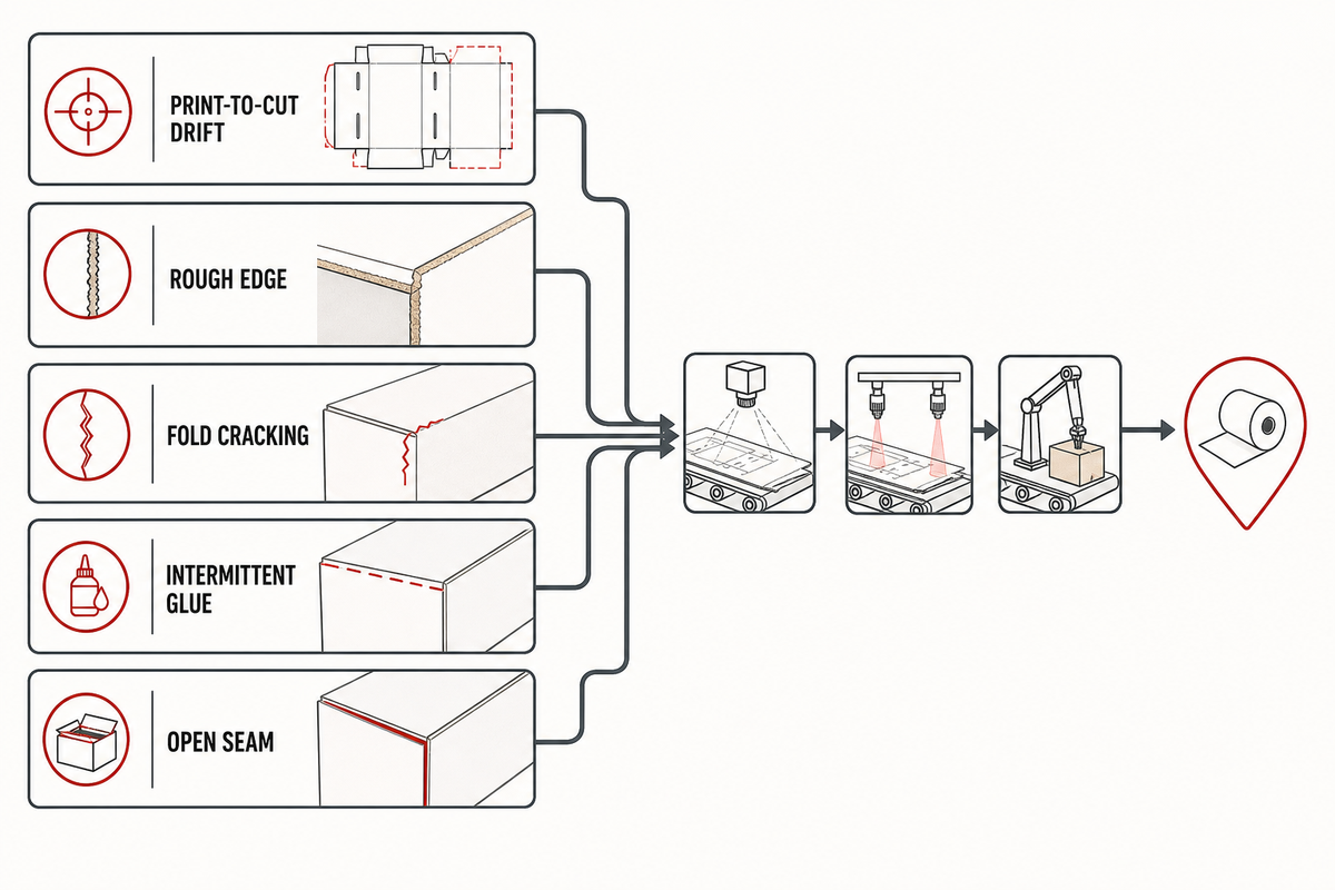
Direct answer: start with the visible defect, freeze the current recipe, and check the earliest controlled variable that could create it. Treat every listed cause as a hypothesis until one change produces a repeatable result. Adjusting the last machine that touched the carton can hide the upstream origin.
Asset 3: Defect-to-Origin Matrix
| Visible defect | First controlled check | Upstream hypotheses | Confirmation test |
|---|---|---|---|
| Print-to-cut drift | Approved sheet against dieline reference | Print register, sheet condition, feed alignment, tool register | Compare sequential samples and one controlled alignment change |
| Rough or fuzzy edge | Cut edge under agreed inspection method | Tool condition, pressure, board construction, debris | Known-good tool/stock comparison |
| Blank breakup or jam | Nick and stripping integrity | Weak nicks, warp, debris, transfer timing, guide position | Trace the first damaged blank upstream |
| Fold cracking | Crease position and stock condition | Grain, moisture, coating, crease geometry, fold path | Approved stock and controlled crease comparison |
| Fishtailing or skew | Blank squareness at fold entry | Cut/crease register, belt tracking, guide symmetry, blank warp | Mark one blank and observe each handoff |
| Missing or intermittent glue | Glue pattern against blank position | Blank timing, sensor state, recipe, nozzle/roller condition | Pattern verification at controlled speed states |
| Squeeze-out or scuff | Joint overlap and glue-free surface | Excess pattern, fold position, coating, pressure path | Separate application from compression variables |
| Open seam after compression | Conditioned seam under agreed test | Surface compatibility, glue placement, fold spring-back, compression path | Production-stock bond trial with one-variable changes |
| Unstable delivered stack | Carton geometry before counting | Fold mismatch, trapped air, seam state, delivery timing | Compare geometry before and after compression |
This is a practical tool for QA because it turns “bad boxes” into a reproducible test. It also helps the plant manager stop teams from changing “all three” variables at once and shows procurement exactly which evidence the supplier needs to present during FAT. If the matrix leads to release sampling, select and document the sampling procedure separately; ISO 28590:2017 provides the introduction to the ISO 2859 attribute-sampling series.
Design the control and safety handshakes
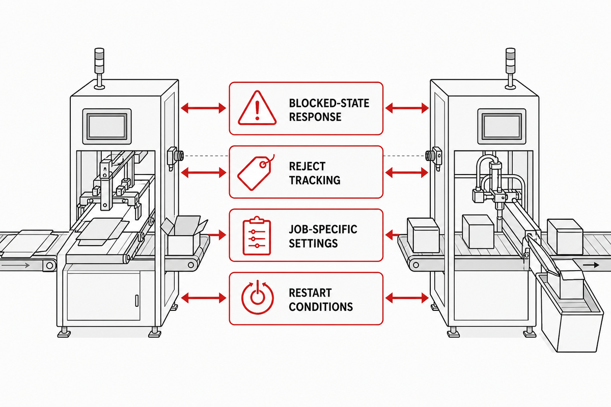
The defect-to-origin matrix shows where a defect begins. Direct answer: define job ID, ready, run, speed reference, starved, blocked, fault, reject, controlled stop, and restart behavior across every module. Then assess operating safeguards separately from servicing energy control. A PLC signal proves a state exchange; it does not prove that every safety risk is controlled.
Controls acceptance should answer four practical questions:
- What happens upstream when a downstream module becomes blocked?
- Can a rejected blank be physically tracked to removal from the line?
- Which settings are following the speed reference and which are job specific?
- Which conditions must be re-established after a fault, an opened guard, or an emergency stop?
OSHA 1910.212 identifies point-of-operation, ingoing nip-point, and rotating-part exposure points within its U.S. general-industry scope. That’s a baseline, not a complete risk assessment for a particular line or jurisdiction.
Servicing is a different state. OSHA 1910.147 addresses hazardous-energy control, including stored or residual energy and verification. A normal-production guard interlock or stop button isn’t automatically an energy-isolating device. Qualified site personnel must define procedures for setup, jam clearing, cleaning, tooling, maintenance, and testing.
ISO 12643 also has scope boundaries: Part 2:2023 covers prepress and press equipment, Part 3:2023 covers binding and finishing equipment, and Part 4:2023 covers converting equipment and systems. Identify the applicable parts; do not treat one part as a blanket conformity certificate.
Safety boundary: this guide doesn’t constitute professional advice, a risk assessment, or an energy-control procedure. Apply current local requirements, machine-validated documentation, and qualified safety engineering to the installed system.
Plan changeovers without hiding startup waste
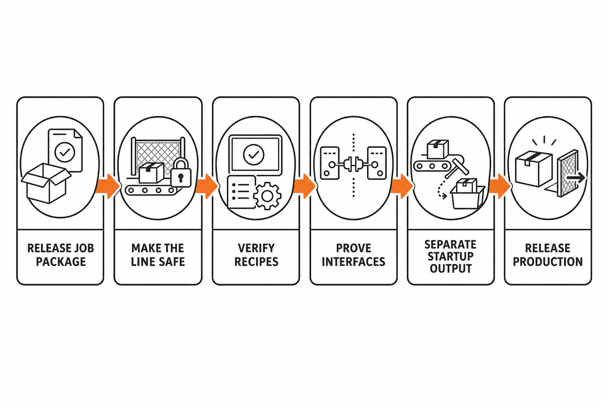
The control and safety states set the boundary for changeover work. Direct answer: a changeover ends when the line reaches a defined stable accepted state, not when tools stop moving. Record setup start, first feed, first conforming carton, stable-run start, accepted count, and startup rejects. Freeze the artwork, dieline, stock, tooling, recipe, glue, inspection method, and release authority beforehand. Use the control and safety states above as the time-recording boundary.
Use one sequence across departments:
- Release the job package: approved artwork, dieline, structure code, material, adhesive, critical-to-quality features, and sampling plan.
- Make the line safe: apply the site’s documented setup and energy-isolation procedure before tooling or access, using the rules applicable to the installed site.
- Load and verify recipes: compare the revision, job ID, and module-specific values before first feed.
- Prove interfaces in order: register, cut/crease, transfer, fold, glue, compression, then delivery.
- Separate startup from stable output: preserve time and reject categories rather than merging them into one shift total.
- Release production: only the named authority signs off against the agreed evidence.
Illustrative timestamp record (not a benchmark): capture setup start, first feed, first conforming carton, stable-run start, release authority, and startup-reject categories. The value comes from consistent timestamps, not a universal “good” changeover duration.
This section intentionally stays at the machine level. Overall line layout, retrofits, and ROI calculations belong to the site’s general packaging-line context while equipment configurations should be on their own commercial solution pages.
Turn FAT and SAT into measurable acceptance tests
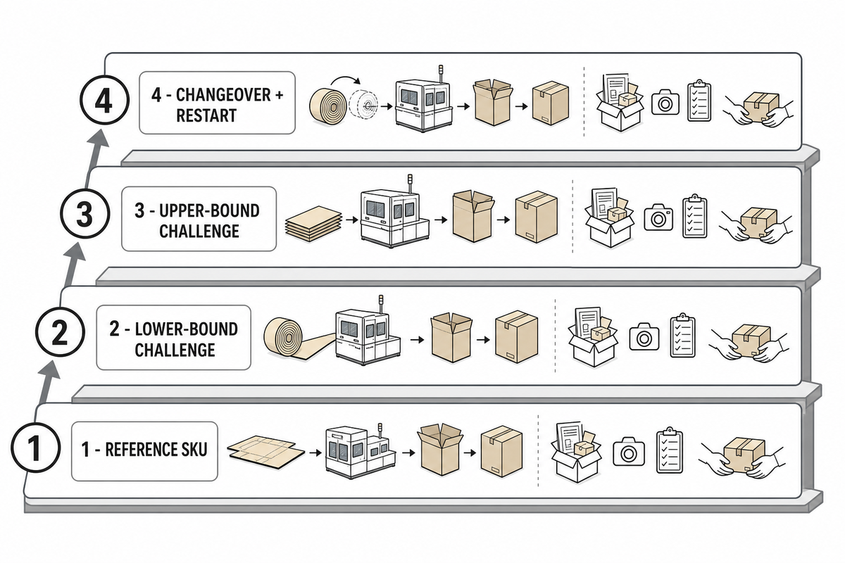
Direct answer: FAT should prove agreed functions, quality checks, stable accepted output, fault behavior, and safety-related acceptance items with defined materials and measurement methods. SAT repeats critical evidence with site utilities, site operators, real connections, and approved stock. Neither test should rely on a short peak-speed demonstration. This carries the preceding machine-level changeover evidence into acceptance testing without pulling plant-wide layout or ROI into the test.
Asset 4: the Four-Lot FAT Ladder
| Lot | Purpose | Buyer-defined inputs | Evidence to retain |
|---|---|---|---|
| 1 — Reference SKU | Prove the normal job and inspection flow | Approved stock, artwork, dieline, adhesive, recipe | Accepted rate, defect categories, stops, samples |
| 2 — Lower-bound challenge | Test one agreed lower product boundary | Named boundary and why it matters | Same evidence fields as reference lot |
| 3 — Upper-bound challenge | Test one agreed upper product boundary | Named boundary and why it matters | Same evidence fields as reference lot |
| 4 — Changeover and restart | Prove recipe, tooling, release, stop, and restart control | From/to jobs, planned stop, fault or safe-stop scenario | Timestamps, startup rejects, state sequence, re-release |
Important boundary: four diverse lots improve coverage, but they do not create a statistical acceptance plan. ISO 28590:2017 introduces multiple attribute-sampling systems and selection of an inspection system for the situation. Buyers must separately define sampling rationale, defect classification, acceptance/rejection rules, and decision risk.
The measurement system also needs evidence. Define the gauge or inspection method, resolution, calibration status, operator method, repeatability, reproducibility where relevant, conditioning, and data recording. No precise-looking tolerance is defensible if the method cannot distinguish acceptable from unacceptable output consistently.
Before FAT, agree the materials, utilities, lot identity, operators, inspection method, stable-run window, stop/restart scenario, guarding checks, open-deviation owner, and retest rule. During SAT, repeat the critical subset with site services and connected upstream/downstream equipment. Universal tolerances do not belong here; the buyer’s product specification owns the values.
Prepare an RFQ interface data sheet
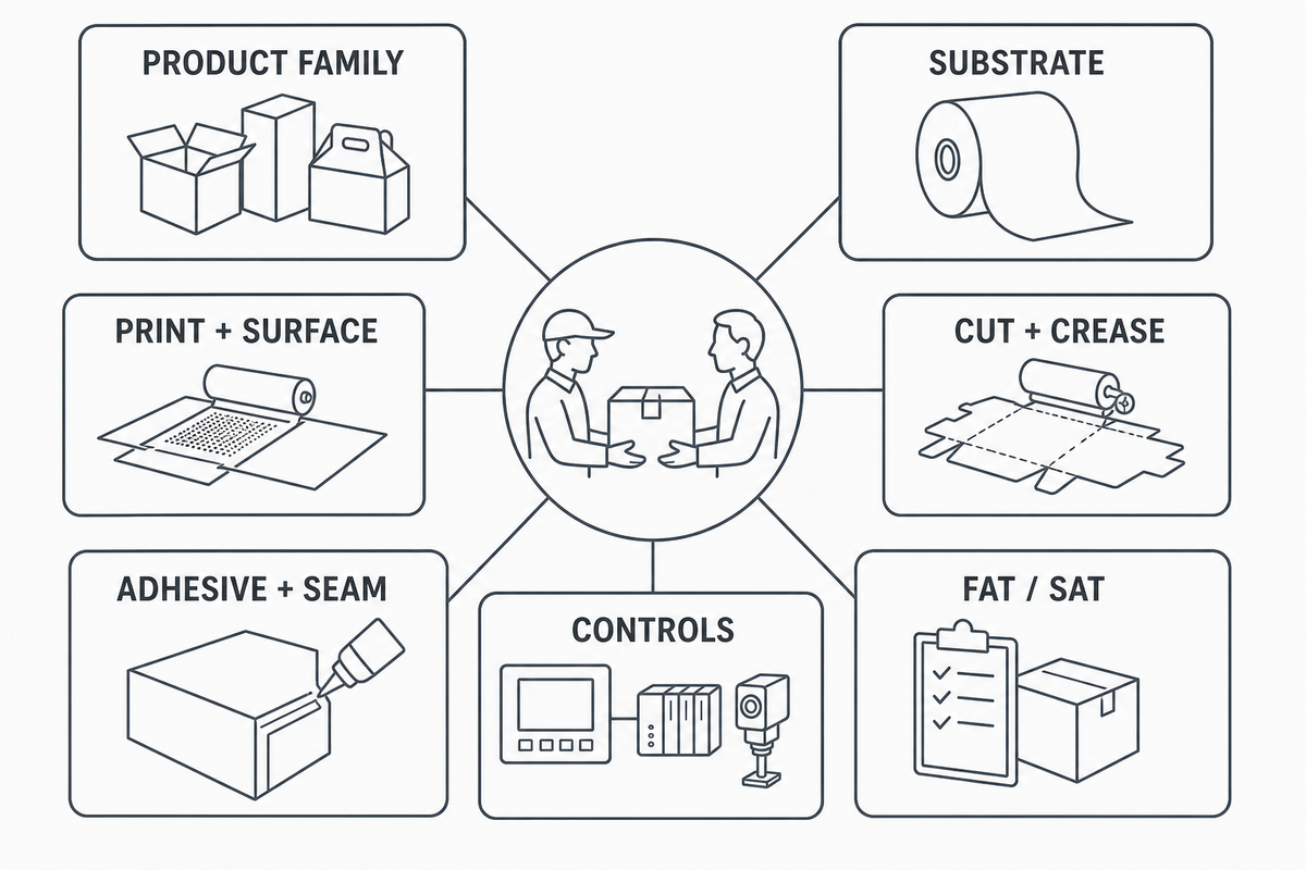
Direct answer: an effective RFQ describes product families, material condition, artwork and dielines, critical quality features, accepted-output demand, changeovers, controls, utilities, inspection, rejects, safety basis, and acceptance materials. A speed-only request leaves the supplier to guess the interfaces that determine whether the connected line can make conforming cartons.
Asset 5: RFQ Interface Data Sheet
| Data group | Fields to provide | Primary buyer owner |
|---|---|---|
| Product family | Carton styles, dielines, FEFCO code where relevant, size range, SKU mix | Procurement + engineering |
| Substrate | Grade, flute, caliper, grain, conditioning, approved suppliers, lot variability | QA + procurement |
| Print and surface | Artwork revision, colors, ink, coating, varnish, glue-free zones | Prepress + QA |
| Cut and crease | Tooling, critical dimensions, register method, crease and blank-integrity evidence | Engineering + QA |
| Adhesive and seam | Approved adhesive, surface, pattern, inspection, conditioning, seam test | QA + supplier specialists |
| Output and losses | Accepted-output target by SKU, shift pattern, changeover mix, reject taxonomy | Plant manager + owner/finance |
| Controls | Job ID, protocols, ready/run/fault states, speed reference, reject tracking, data retention | Automation engineering |
| Utilities and environment | Electrical, air, extraction, temperature/humidity controls, site constraints | Facilities + engineering |
| Safety basis | Jurisdiction, applicable standards, guarding, access, energy isolation, acceptance responsibility | Qualified safety owner |
| FAT/SAT | Lots, sample plan, methods, stable window, deviations, retest, SAT subset | QA + procurement + plant manager |
Freeze the metric units before suppliers quote
These are field formats, not target values. Select units that fit the buyer’s specification and jurisdiction, then use the same definitions in every FAT and SAT record.
| Metric category | Possible unit | Definition to freeze |
|---|---|---|
| Accepted output | cartons/hour | Good cartons after the agreed inspection rule |
| Availability | % | Included and excluded time states |
| First-pass yield | % | Denominator, rework handling, and defect classes |
| Changeover | minutes/job | Start and end events |
| Micro-stop loss | minutes/shift | Minimum stop capture and classification |
| Buffer capacity | blanks | Usable accumulation without damage |
| Board caliper | mm | Method, conditioning, and sampling location |
| Registration deviation | mm | Datum, direction, tool, and sample plan |
| Air pressure | kPa | Measurement point and operating condition |
| Connected load | kW | Included modules and auxiliaries |
| Energy per job | kWh/job | Job boundary and idle-time handling |
| Adhesive application | g/m² or mL/min | Approved method and pattern area |
| Conditioning temperature | °C | Location, stabilization time, and range |
| Relative humidity | % RH | Location, stabilization time, and range |
2026 operational outlook
Current qualitative signals from PMMI and PostPress include further system integration, digitally linked capabilities, workforce support, lifecycle planning, and supplier collaboration. A practical response is not to claim a universal speed gain. It is to request better job data, interface states, fault data, changeover evidence, and maintainable controls in the RFQ.
When an integrated line is the right solution
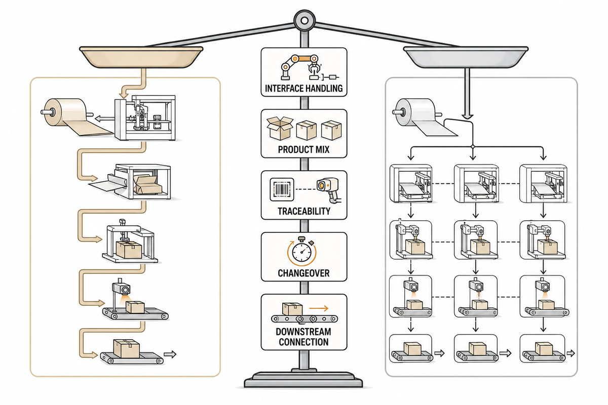
RFQ evidence makes the integration choice concrete. Direct answer: integration fits when repeated handoffs create avoidable alignment, traceability, labor, or scheduling losses and the product mix is stable enough to define controlled recipes and changeovers. Stand-alone equipment may remain sensible when work is highly variable, shared across routes, or intentionally buffered between processes.
| Decision factor | Evidence favoring integration | Evidence favoring a separated route |
|---|---|---|
| Interface handling | Frequent damage, mixing, alignment, or WIP ambiguity | Deliberate curing, drying, inspection, or queue buffer |
| Product mix | Repeat families with defined boundary formats | Routes and processes change job by job |
| Traceability | One job identity and reject trail must cross every module | Independent batch release is intentional |
| Changeover | Coordinated recipes reduce repeated setup proof | Parallel independent setups protect flexibility |
| Downstream connection | Counting, packing, or palletizing needs synchronized delivery | Multiple downstream destinations require decoupling |
When your interface data is ready, compare it with CENWAN’s integrated printing-to-gluing line solution. Use that commercial page for configuration and inquiry, and keep this guide as the engineering checklist behind the conversation.
For supplier context, review CENWAN’s company and manufacturing background, then verify every project-specific claim against the RFQ evidence and acceptance plan.
Frequently asked questions
Direct answer: the useful questions are not only “How fast is the line?” but “What counts as accepted output?”, “Which data cross each interface?”, “How are defects traced?”, and “What must FAT and SAT prove?” Together, these questions turn RFQ evidence into an acceptance plan. The answers below are starting points; final values belong in the buyer’s specification. For line-balance background, the NIST analysis of product-mix performance in serial lines explains why sequence, buffers, processing times, and blocking matter.
How does a printing die cutting folding gluing line work?
View answer
Sheets or blanks move through registered printing, cutting and creasing, controlled transfer, folding, timed adhesive application, compression, counting, and delivery. Every station must share the correct job identity, recipe, state signals, reject rules, and release evidence. The line succeeds when conforming cartons leave at a stable accepted rate; the fastest individual module does not define the connected process.
What should be included in a FAT for an integrated carton line?
View answer
Define substrates, artwork, dielines, adhesive, utilities, operators, test lots, inspection methods, measurement capability, sampling logic, defect rules, stop/restart scenarios, safety checks, and recorded data before testing. Run a reference lot, agreed boundary formats, and a controlled changeover. Report accepted output and defect categories over an agreed stable window. Preserve the original records, open deviations, responsible owners, retest conditions, and the critical results that must be repeated during SAT with site utilities and operators.
How do you find the bottleneck in a printing-to-gluing line?
View answer
Compare each station and interface under the same job and time window, then classify losses as starvation, blockage, planned stop, changeover, reject, or fault. The bottleneck is the constraint that repeatedly limits accepted delivery, not automatically the lowest catalogue speed. Change one condition and watch whether accepted output follows it. Recheck the conclusion across the planned product mix because build sequence, finite buffers, different processing times, and downstream blocking can move the active constraint from one interface to another.
Can coatings or varnishes cause glue failure?
View answer
Yes, they can change the surface presented to the adhesive. Still, the seam must be traced through glue placement, fold alignment, compression, conditioning, and stock variation. Test approved printed production stock with the responsible material specialists.
When is an integrated line better than stand-alone equipment?
View answer
Integration becomes more compelling when repeated transfers create alignment, traceability, labor, work-in-process, or scheduling losses and when product families can be expressed as controlled recipes. It can also help when downstream counting or packing requires synchronized delivery and one reject identity must follow the carton. Separate equipment may be more practical when jobs follow different routes, require intentional drying or inspection buffers, depend on shared machines, or need independent queues to protect plant flexibility. Compare the interface-loss evidence, not just the number of operators or the fastest module.
References and sources
- University of Bologna ADU, Folding-Gluing
- NIST, Multi-Job Production Systems and Product-Mix Performance
- OSHA 1910.212, General Requirements for All Machines
- OSHA 1910.147, Control of Hazardous Energy
- OSHA, Printing Industry Lockout/Tagout Interpretation
- ISO 12643-2:2023, Prepress and Press Equipment
- ISO 12643-3:2023, Binding and Finishing Equipment
- ISO 12643-4:2023, Converting Equipment and Systems
- ISO 28590:2017, Introduction to Attribute Acceptance Sampling
- Holmen Iggesund, Die-Cutting and Creasing
- FEFCO, FEFCO Code
- PMMI, 2026 From Complexity to Capability
- PostPress, The State of Folding Cartons Today and What’s Ahead
Source note: standards links establish publication scope, not certification of a specific machine or installation. Holmen Iggesund and CENWAN are commercial/first-party sources and are used only within the limits stated in the article. No competitor performance, price, or ROI claim is used.
Manufacturer Background
Cenwan Machine is a Wenzhou, China-based manufacturer of folder gluer machines, corrugated box gluing equipment, and integrated packaging lines. For more than 10 years, we have supported carton and corrugated packaging manufacturers in 40+ countries with equipment selection, custom configuration, installation support, spare parts, and after-sales service.
Our blog content is written to help packaging buyers, plant managers, and procurement teams understand folder gluer technology, box style compatibility, production capacity, ROI, maintenance, and supplier selection before requesting a quote.
- 10+ years of folder gluer engineering experience
- Factory base in Ruian, Wenzhou, Zhejiang, China
- Folder gluer machines, corrugated folder gluers, and automatic packaging lines
- CE / ISO 9001 manufacturing and quality references
- Remote diagnostics, spare parts support, and 24/7 technical response
- Equipment and service experience across 40+ countries
Brand
Cenwan Machine
Company
Zhejiang Chengwang Intelligent Packaging Equipment
Business Type
B2B Machinery Manufacturer
Factory Base
Ruian, Wenzhou, Zhejiang, China
Email
sales2@cenwanmachine.com
Phone / WhatsApp
+86 139 0664 6788